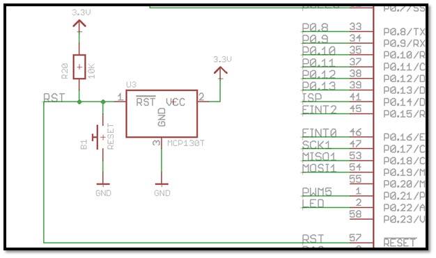
All signals are marked with suitable legends.

Bus Signals All Address, Data and Control signals are terminated in 50 pin berg stick for user expansion.Display Six numbers of bright seven-segment displays for address and data.Keyboard Consists of 28 numbers of keys with tops.RST 7.5 and TRAP are available to the user if VECT-INTR & SINGLE STEP functions are disabled. TRAP is used for single instruction step function RST5.5 is used for keyboard operation. Interrupt RST7.5 is used to provide keyboard VECT-INTR function.Counter 1 is used for serial I/O baud rate generation. Timer Three 16-bit counter/timer using 8253 programmable timer.These lines are terminated in a 9-pin D type female connector. I/O Serial One RS-232C compatible interface, using USART-8251A with programmable baud rates through 8253 programmable timer.


 0 kommentar(er)
